
Actuators
An actuator is a DC or BLDC motor with its gear; it drives one joint of an articulated system. On this page, "motor" means only the electric part of an actuator (its resistance, torque constant, speed and torque). RaiSim limits the torque of every actuator to what its motor can actually produce: the motor operating region (MOR), which depends on the motor speed, the bus voltage and the peak torque.
The URDF <limit effort velocity> of a joint describes a rectangle in the torque-speed plane. Kim et al. call it the Box-MOR in "Reinforcement Learning for High-Speed Quadrupedal Locomotion With Motor Operating Region Constraints" (IEEE Robotics & Automation Magazine, 2025). A real motor cannot use that whole rectangle. While it drives a load, the back EMF eats into the bus voltage, so the available torque drops with speed. While it brakes, the back EMF adds to the bus voltage and more torque is available than the rectangle allows. Policies trained with the Box-MOR exploit torques that the real motors cannot deliver at high speed. Training with the electro-mechanical MOR (EM-MOR) removes that sim-to-real gap.
RaiSim:
- reads actuators from the URDF (an
<actuator>element links an actuator file, just like a<link>links a sensor file) or from C++, - takes one torque per actuator (
setActuatorTorques()) and, every step, clips each actuator's motor torque to its EM-MOR. The region limits only the torque: external forces and torques can still drive a motor at any speed, - lets an actuator's motor also turn with other joints (couplings), e.g., a knee motor on the body that drives the knee through a reducer turning with the thigh, and
- reports the speed and the MOR-limited torque of every actuator's motor.
The MOR applies only to actuator torques. Torques from setGeneralizedForce(), the built-in PD controller, damping, springs and friction add on top and are not clipped by it, and the joint effort limits do not clip actuator torques (see What happens in a simulation step).
The motor model
Under quasi-static conditions (the current changes slowly compared to the simulation step, the same assumption as a dynamometer torque-speed curve), the voltage over a DC motor is
with the winding resistance
All values are on the motor (rotor) side of the reducer and in SI units.
The electromagnetic torque <dynamics friction damping> with the same model (see Joint Damping and Friction). For an actuator with gear ratio
and at rest the friction holds the joint as long as the other torques on it stay below
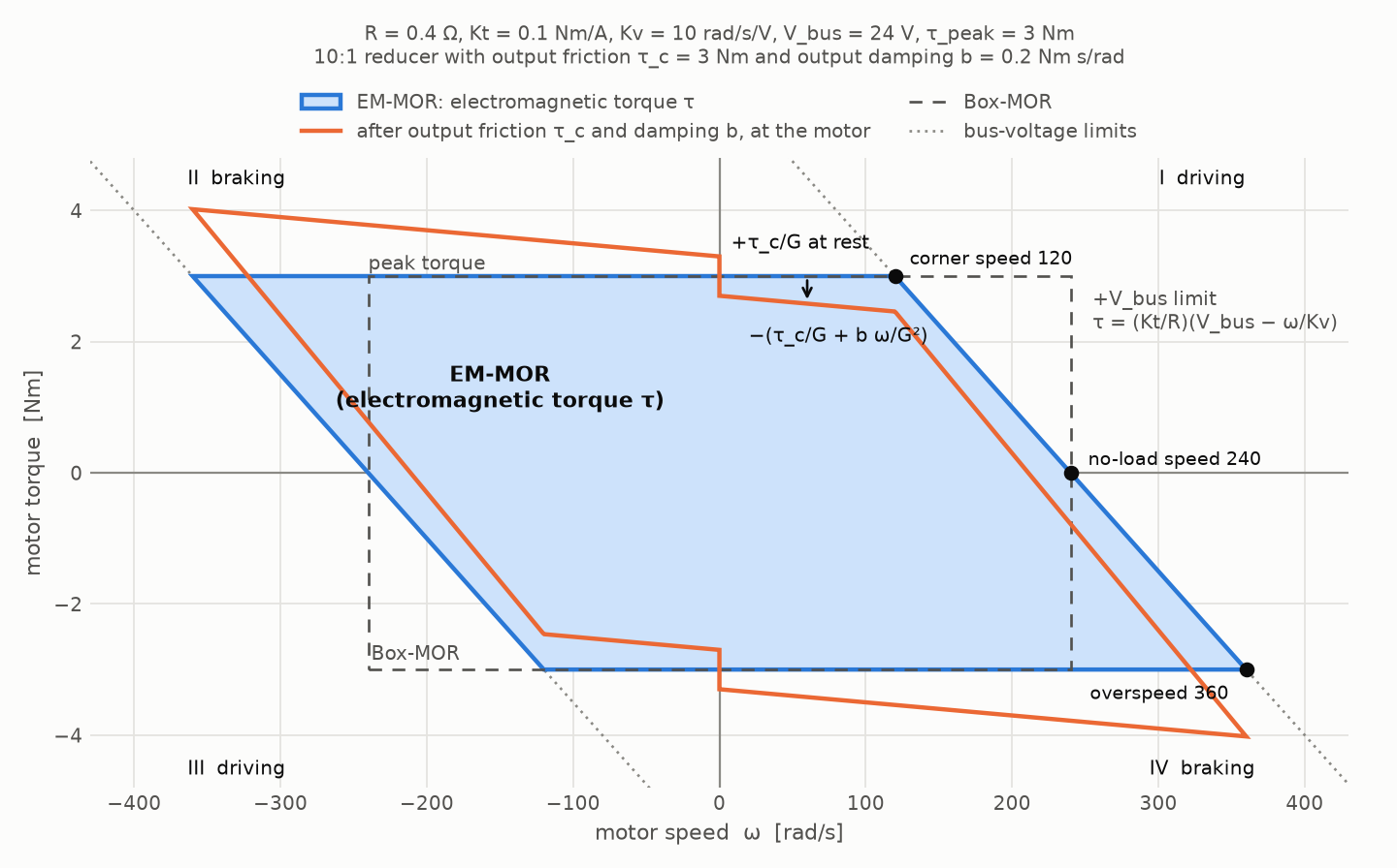
The region is a parallelogram. Its slanted edges are the bus-voltage limits, its horizontal edges the peak torque. Several speeds characterize it:
| Quantity | Value | Meaning |
|---|---|---|
| stall torque | voltage-limited torque at zero speed | |
| no-load speed | the motor cannot drive faster | |
| corner speed | above it, the voltage limit (not the peak torque) limits driving | |
| overspeed limit | above it, even full reverse voltage drives more than the peak current | |
| back-EMF damping | slope of the voltage limit; a motor at its voltage limit acts as a damper |
The region defines which torque the motor can produce at a speed; it does not limit the speed. External forces and torques, e.g., a foot impact or gravity on a falling leg, can back-drive a motor beyond its no-load speed, where only braking torque is left. Beyond the overspeed limit the peak-torque band and the voltage band no longer overlap: every voltage the driver can apply drives more than the peak current against the back EMF. The saturated core caps the torque, so the only torque left is the peak torque against the rotation, and the region continues as the line
Defining actuators in a URDF
An <actuator> element, placed directly under <robot>, puts one actuator on one joint. The actuator's model (its gear ratio, its output losses and its <motor>) usually lives in its own file with an <actuator_model> root, so that one model can be shared by all joints and robots that use it:
<robot name="quadruped">
  ...
  <actuator joint="LF_HAA" file="abduction_actuator.xml"/>
  <actuator joint="LF_HFE" file="hound_leg_actuator.xml"/>
  <actuator joint="LF_KFE" file="hound_leg_actuator.xml">
    <coupling joint="LF_HFE" ratio="1"/>
  </actuator>
</robot>actuators/abduction_actuator.xml, a motor behind a 6:1 reducer:
<actuator_model name="abduction_6to1" gear_ratio="6">
  <motor resistance="0.4" torque_constant="0.1" velocity_constant="10" bus_voltage="24"
         peak_torque="3"/>
</actuator_model>actuators/hound_leg_actuator.xml, the same motor behind a 10:1 reducer, used for the hip and the knee. The knee motor also turns with the hip, which its <coupling> declares (see Couplings):
<actuator_model name="hound_leg" gear_ratio="10">
  <motor resistance="0.4" torque_constant="0.1" velocity_constant="10" bus_voltage="24"
         peak_torque="3"/>
</actuator_model>
The actuator file is searched like a sensor file: first in the directory of the URDF file, then in [urdf_dir]/actuator, [urdf_dir]/actuators, [urdf_dir]/.. and [urdf_dir]/../actuators. For a URDF given as a string, the resource directory passed to World::addArticulatedSystem() takes the place of [urdf_dir].
Instead of linking a file, the model can be written on the <actuator> itself. This is convenient for URDF strings and quick experiments:
<actuator joint="wheel" gear_ratio="8">
  <motor resistance="0.2" torque_constant="0.1" back_emf_constant="0.1" bus_voltage="48"
         peak_torque="1.5"/>
</actuator>
RaiSim reads only its own <actuator> elements. The ROS <transmission> and Gazebo elements that many URDFs contain are ignored.
<actuator>
| Attribute or child | Meaning |
|---|---|
joint | the driven joint (required). It must be a revolute (or continuous) or prismatic joint, and each joint can be driven by only one actuator. |
name | actuator name, unique within the robot (default: the joint name, see Actuator names) |
file | actuator file with an <actuator_model> root. Without it, the <actuator> holds the model itself: the <actuator_model> attributes and its <motor>. |
model | model name of an inline model (informational). A linked file gives the name of its <actuator_model> instead. |
<coupling> | another joint the motor also turns with (optional, any number, see Couplings) |
<actuator_model>
| Attribute or child | Meaning |
|---|---|
name | model name, reported by ActuatorDefinition::model (informational) |
gear_ratio | gear ratio |
output_damping | viscous damping of the actuator measured at its output [Nm s/rad] (optional, default 0). It adds to the damping of the driven joint. |
output_friction | Coulomb friction torque of the actuator measured at its output [Nm] (optional, default 0). It adds to the friction of the driven joint. |
<motor> | the motor inside the actuator (exactly one) |
<motor>
| Attribute | Meaning |
|---|---|
resistance | winding resistance |
torque_constant | |
velocity_constant | |
back_emf_constant | velocity_constant and back_emf_constant. |
bus_voltage | bus voltage |
peak_torque |
<coupling>
| Attribute | Meaning |
|---|---|
joint | a revolute or prismatic joint other than the driven one (required). It does not need an actuator of its own. |
ratio | motor speed per unit speed of that joint (required, finite, any sign) |
Datasheets often list
output_damping and output_friction are joint-side values: the friction and damping you measure at the joint, e.g., by back-driving it. They act on the driven joint. In the Hound leg (see Couplings), this is also where the knee reducer's gears move: its ring gear turns with the thigh, so its meshes slide with the knee speed, not with the knee motor speed. RaiSim adds them to the joint's own <dynamics friction damping>, so you can keep losses in either place or split them. The rotor inertia is still set at the joint with <dynamics rotor_inertia> as the reflected inertia
Bus voltage
The bus voltage belongs to the power supply, not to the motor: all motors on one battery see the same voltage, and it sags together as the battery drains. Every actuator that links the same model file gets the voltage of its <motor>.
The voltage can be changed at runtime with a single call, for example to follow the battery voltage or to randomize it during training. It only changes the stored voltage and can be called every step:
robot->setBusVoltage(46.5);            // all actuators
robot->setBusVoltage("LF_KFE", 46.5);  // one actuator, by name
Actuator names
Every actuator has a name that is unique within the articulated system: its name attribute, or the name of its joint. getActuatorNames() lists the actuators in the order of the <actuator> elements; getActuatorIndex(name) returns the position of a name.
Errors
Invalid actuators are fatal errors. Errors in an actuator file or an <actuator> element name the file and row: a missing joint or gear_ratio, a gear ratio that is not positive, a missing or doubly given motor constant, a missing bus voltage, a non-positive or non-finite motor parameter, negative output losses, a model without exactly one <motor>, a <coupling> without a joint or a finite ratio, a missing actuator file, and an <actuator> with both a file and an inline model. When the robot is built, RaiSim also rejects an unknown, fixed or spherical joint (driven or coupled), a joint driven by two actuators, a coupling to the driven joint itself or twice to one joint, and duplicate actuator names.
Couplings
An actuator's motor turns with its joint through the gear, <coupling> adds another joint that the motor also turns with:
By conservation of power,
KAIST Hound (the robot of the paper) puts the hip (HFE) and the knee (KFE) motor of a leg on the body. The hip motor turns the thigh through a planetary reducer with ratio
the knee actuator has the gear ratio
<actuator joint="LF_KFE" file="hound_leg_actuator.xml">
  <coupling joint="LF_HFE" ratio="1"/>
</actuator>
The knee motor torque also loads the hip:
Written for all actuators and joints at once, the gear and coupling ratios form the transmission matrix
[ w_hip_motor  ]   [ G_H   0  ] [ u_HFE ]
[ w_knee_motor ] = [  1   G_K ] [ u_KFE ]
A coupling changes which torque a motor can apply and where its torque goes. It does not tie the joints together: every joint keeps its degree of freedom, and the dynamics are still computed for the joints. A mechanism that does tie joints together, e.g., one motor that drives two joints through a linkage, is a constraint between the joints and cannot be described with couplings.
The rotor inertia is the one place where a coupling would also change the dynamics. The kinetic energy of the motors, rotor_inertia in <dynamics>), so this term is not simulated. Set rotor_inertia to the diagonal of
What happens in a simulation step
The operating region applies to the actuator torques and only to them. At the beginning of every step, with the joint velocities setActuatorTorques()) computes its motor speed, the bounds of its region at that speed and its motor torque:
with the stall torque
is set with setGeneralizedForce()andis the built-in PD torque. Only this sum is clamped to the actuation limits (URDF effortorsetActuationLimits()).is the joint's own damping and the actuator's output damping. and are the joint velocity at the beginning and at the end of the step. Damping is passive and is never clipped. It is integrated with the trapezoidal rule (see Joint Damping and Friction). is the joint friction (the joint's own plus the actuator's output friction). The contact solver solves it together with the contacts, as an impulse bounded by that stops the joint or opposes its motion. This also applies to joints without an actuator. - Springs, external forces and contacts are not clipped either, and the sum is not clamped again.
The PD controller and the springs are integrated implicitly, and the clamp bounds only the explicit part of the PD torque. Joint torque of a simulation step in the articulated system section writes out every term.
Joint effort limits and MOR are separate limits: effort limits do not clip actuator torques, and MOR does not clip the generalized force or the built-in PD torque. For example, take a turntable joint spin with a 5 Nm effort limit and no PD, damping, springs or external forces, driven by the actuator spin (gear ratio 10;
robot->setGeneralizedForce(Eigen::VectorXd::Constant(1, 100.));
robot->setActuatorTorque("spin", 100.);
The generalized force contributes 5 Nm and the actuator 15 Nm, 20 Nm in total. At a joint speed of 23.8 rad/s (238 rad/s at the motor, just below its 240 rad/s no-load speed), the voltage limit allows only the 12 Nm stall torque minus the back-EMF damping times the speed,
Because the actuator torques are fixed for the step, contacts and impacts cannot push them out of the region. Compare an applied motor torque with the region at the speed at the beginning of the step, ActuatorState::motorSpeed.
A controller should therefore send its torques as actuator torques. RaiSim's built-in PD controller acts on the joints and is not an actuator torque; to keep a PD controller inside the operating regions, compute it explicitly and send the result with setActuatorTorques().
Time step and the voltage limit
At the voltage limit the torque falls with the speed: the motor acts as a damper of
with rotor_inertia in <dynamics>). The reflected rotor inertia usually dominates, so the bound is about twice the motor's own mechanical time constant
Accuracy
The applied motor torques are the commanded ones clipped to their regions, so they lie inside the regions to round-off, also under foot impacts. The tests check this to
Commanding actuator torques
Every actuator takes one torque, at the output of its gear:
// one entry per actuator, in this order:
// {"LF_HAA", "LF_HFE", "LF_KFE", "RF_HAA", ...}
const auto& names = robot->getActuatorNames();

robot->setActuatorTorques(torques);        // Eigen::VectorXd, one torque per actuator
robot->setActuatorTorque("LF_KFE", 12.);   // one actuator, by name
robot->setActuatorTorque(2, 12.);          // the same actuator, by index
The order and the names are described in Actuator names. The same order is used by getActuators(), getActuatorTorques(), getActuatorTorqueBounds() and getActuatorStates().
The torque is at the output of the actuator's gear: its motor torque times its gear ratio. It is the torque on the driven joint. An actuator with couplings also applies its motor torque times the coupling ratio to each coupled joint: 12 Nm on the Hound knee is a knee motor torque of 1.2 Nm, which also loads the hip with 1.2 Nm.
The actuator torques hold until they are set again. getActuatorTorques() returns the torques that were set; getActuatorStates() reports what the motors applied. getGeneralizedForce() returns the effort-clipped generalized force and built-in PD contribution plus the mapped actuator torques clipped to MOR at the current motor speeds. It excludes passive damping, springs and friction, and its built-in PD contribution is approximate because PD is integrated implicitly.
Actuator torque bounds
getActuatorTorqueBounds(lower, upper) returns, per actuator, the torques it can apply now, at the output of its gear: its motor's region at the current motor speed, times its gear ratio. These are exactly the bounds to which the next step clips setActuatorTorques(). Use them, e.g., to scale a policy's actions into the admissible range:
raisim::VecDyn lower, upper;
robot->getActuatorTorqueBounds(lower, upper);  // [Nm or N], getActuatorNames() order
for (size_t i = 0; i < robot->getActuatorNames().size(); ++i)
  torques[i] = 0.5 * (lower[i] + upper[i]) + 0.5 * (upper[i] - lower[i]) * action[i];  // action in [-1, 1]
robot->setActuatorTorques(torques);
With the region not enforced (see Monitoring without enforcing), the bounds are infinite.
Reading the actuator states
getActuatorStates() returns one raisim::ActuatorState per actuator for the last step. Except for jointLossTorque, its fields describe the actuator's motor, on the rotor side of the gear. Multiply a motor torque by the gear ratio to get the actuator torque on the driven joint, and by a coupling ratio to get the torque on a coupled joint.
| Field | Meaning |
|---|---|
motorSpeed | motor speed at the beginning of the step [rad/s]; the region of the step is evaluated at it |
averageMotorSpeed | motor speed averaged over the step [rad/s]; motorTorque * averageMotorSpeed is the mechanical power of the motor |
commandedMotorTorque | motor torque requested with setActuatorTorques() (the actuator torque divided by its gear ratio) [Nm] |
motorTorque | electromagnetic motor torque |
jointLossTorque | friction and damping torque on the driven joint over the step [Nm, at the joint]: the joint's own plus the actuator's output losses. It opposes the joint motion. |
saturation | NONE, PEAK_TORQUE or VOLTAGE: the bound that limited the command |
The states are computed at the end of integration and describe that completed step. A subsequent setState() reset does not mix new velocities into the previous step. Concurrent reads are supported while no thread integrates or changes the actuator configuration; synchronize readers with those mutations.
To check the region, or to use the motor torques in a reward (power, saturation penalties):
const auto& states = robot->getActuatorStates();
const auto& actuators = robot->getActuators();
for (size_t i = 0; i < states.size(); ++i) {
  // [Nm], zero inside the region
  const double outside = raisim::motorOperatingRegionViolation(
      actuators[i].motor, states[i].motorSpeed, states[i].motorTorque);
  // mechanical power of the motor [W]
  const double power = states[i].motorTorque * states[i].averageMotorSpeed;
}
The free functions raisim::motorTorqueBounds(parameters, speed) (the admissible torque interval at a speed), raisim::clipMotorTorque(parameters, speed, torque) and raisim::motorOperatingRegionViolation(parameters, speed, torque) work on the motor alone, without its gear: they take a rotor-side speed and a rotor-side torque, like the ActuatorState fields. For torques at the gear output, i.e., in the units of setActuatorTorques(), use getActuatorTorqueBounds() (see Actuator torque bounds).
Monitoring without enforcing
setMotorOperatingRegionEnforced(false) applies the actuator torques as commanded, without clipping (monitor mode), and getActuatorStates() still reports the motor quantities, including the bound that the command exceeds. This reproduces the paper's comparison: run a controller without the motor operating region and measure how far it leaves the region. The output friction and damping still act, and the effort limits still clamp only the feedforward and PD torque.
C++ API
An ActuatorDefinition is the C++ form of one <actuator> element with its model: name (empty: the joint name), model, joint, gearRatio, the couplings (each an ActuatorCoupling with a joint and a ratio), the motor (DcMotorParameters), and outputDamping and outputFriction.
To change only the bus voltage, use setBusVoltage() (see Bus voltage). Other parameters, such as a randomized winding resistance, are changed by editing the definitions and setting them again. setActuators() replaces all actuators, including those from the URDF, and resets every actuator torque to zero:
auto actuators = robot->getActuators();
for (auto& actuator : actuators)
  actuator.motor.resistance *= uniform(0.9, 1.1);
robot->setActuators(actuators);
A Hound knee from scratch:
raisim::ActuatorDefinition knee;
knee.joint = "LF_KFE";
knee.gearRatio = 10.;
knee.couplings = {{"LF_HFE", 1.}};  // the knee motor also turns with the hip
knee.motor.resistance = 0.4;
knee.motor.torqueConstant = 0.1;
knee.motor.velocityConstant = 10.;
knee.motor.busVoltage = 24.;
knee.motor.peakTorque = 3.;
robot->setActuators({knee});
raisim::ArticulatedSystem
| Method | Purpose |
|---|---|
setActuators(actuators) | replace the actuators (one ActuatorDefinition per actuator) and zero their torques; an empty vector removes them |
getActuators() | the actuator definitions, with their names and the bus voltages set since |
getNumberOfActuators(), getActuatorNames(), getActuatorIndex(name) | number of actuators, their names in the order used by all per-actuator methods, the index of a name (size_t(-1) if unknown) |
setActuatorTorques(torques), setActuatorTorque(name or index, torque) | set actuator torques at the gear outputs; they hold until set again |
getActuatorTorques() | the actuator torques as set |
getActuatorTorqueBounds(lower, upper) | admissible actuator torques at the gear outputs at the current motor speeds |
setBusVoltage(voltage), setBusVoltage(actuatorName, voltage) | change the bus voltage of all actuators or of one |
getActuatorStates() | motor speeds and torques of the last step |
setMotorOperatingRegionEnforced(enforce), isMotorOperatingRegionEnforced() | clip to the region (default) or only monitor it |
A change to the actuators wakes a sleeping robot only if it changes the force on it: a changed actuator torque, a bus voltage or enforcement change while an actuator torque acts, or setActuators() while an old actuator torque was nonzero or when the output losses change.
Actuators are part of world checkpoints (World::captureCheckpoint()), so changing them between a capture and a restore is undone by the restore.
raisimGymTorch and raisim_engine2
Actuators are part of the URDF, so a world.xml that refers to the URDF brings them along. World::exportToXml() also writes the current actuators of every articulated system into an <actuators> element of its entry: actuators set with setActuators(), bus voltages changed at run time, nonzero actuator torques and the monitor mode. Each is an <actuator> with its model inline and, if nonzero, a torque attribute. Loading that world.xml replaces the URDF's actuators with them. raisim_engine2's Export for raisimGymTorch bundles linked actuator files together with the URDF, like sensor files, so the exported package loads with its actuators on another machine.
In a raisimGymTorch environment, scale the policy's actions with getActuatorTorqueBounds() before setActuatorTorques(), and read getActuatorStates() after world->integrate() to add the motor speeds or the saturation to the observation, or to penalize torques that saturate the motors.
Example
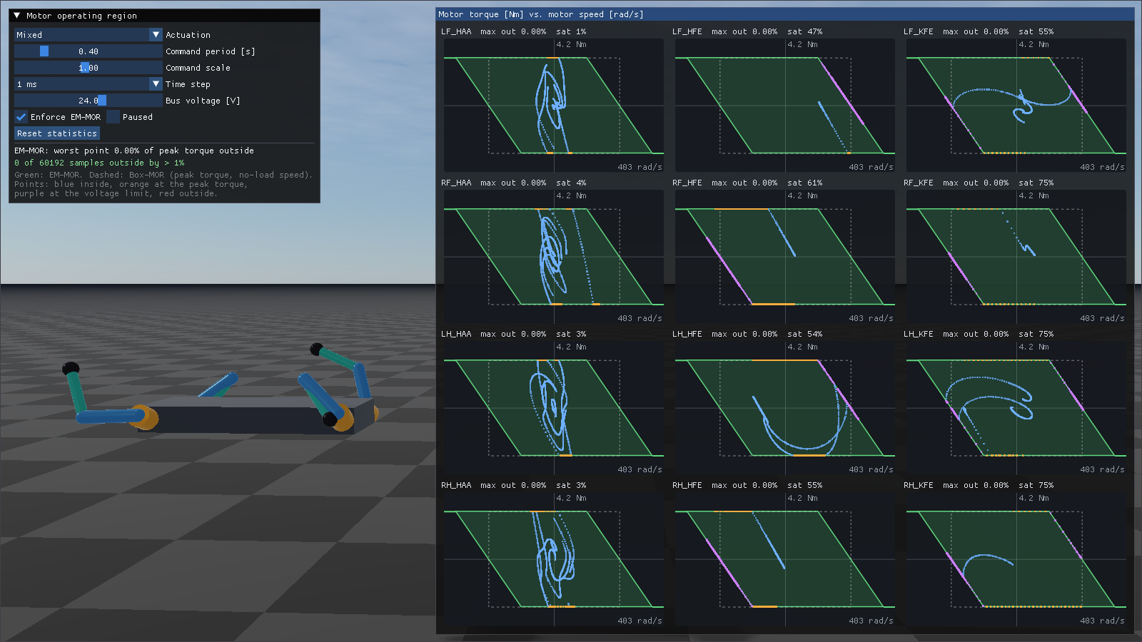
rayrai_motor_operating_region drives the twelve actuators of a fixed-base quadruped rig randomly and plots the operating regions and operating points of their motors. See Rayrai Example: Motor Operating Region.
API
raisim::DcMotorParametersraisim::ActuatorDefinitionraisim::ActuatorCouplingraisim::ActuatorStateraisim::MotorSaturationraisim::MotorTorqueBounds
The ArticulatedSystem methods are documented with the class in ArticulatedSystem API.
The following free functions work on the motor alone (rotor-side speed and torque, without the gear):