
Rayrai Example: FEM Workbench
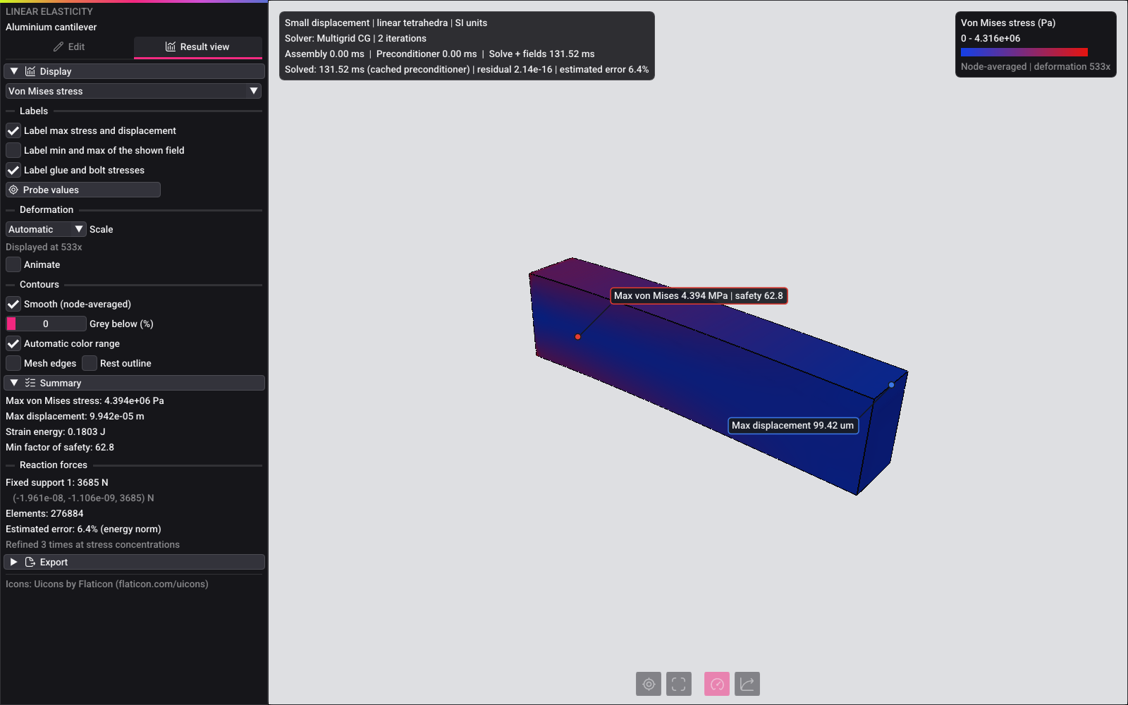
Open a B-rep CAD solid, click its faces to apply supports and loads, and inspect displacement, stress, and strain. The example uses RaiSim's single-threaded linear static FEM solver and renders its results with Rayrai. It opens with a solved aluminium cantilever.
Use this page's Run on web button to run the same C++ workbench in the browser. The site uses its existing web-examples/example.html?example=rayrai_fem_workbench launcher. Uploaded models and calculations remain on the visitor's computer.
Workflow
The Edit and Result view buttons at the top of the panel switch modes. Edit shows the undeformed solid with its supports and loads; its controls are grouped in tabs, one per task:
| Tab | Contents |
|---|---|
| Model | open, add or drop CAD files, units, element size, refinement and mesher settings |
| Parts | the parts, their visibility, materials, removal |
| Loads | face selection, supports and loads |
| Connect | glue, bolts and joints between parts |
| File | save and load projects |
The panel switches to the Parts or Loads tab after a file opens. Result view shows the deformed, colored solid and the display, summary and export controls.
- Drop a STEP, IGES or BREP file on the window, or choose Open CAD in the Model tab. A dropped file joins a CAD model that is already open (see Assemblies); Open CAD replaces it. Only B-rep solids open; mesh files are rejected. Set Metres per BREP unit before opening a BREP (use
0.001for millimetres); STEP and IGES carry their units. The CAD opens as its tessellated B-rep faces, without tetrahedra, and the camera orbits its bounds center. - Dark lines mark the boundaries between CAD faces. Click a face in the 3D view. The whole CAD face is selected and turns amber; hovering shows which face is under the pointer. Ctrl+click or Shift+click adds or removes faces, and clicking empty space clears the selection. See Navigating the view for rotating and zooming. Faces keep their CAD identity after meshing, so the same faces stay selectable on the volume mesh. Select by coordinates selects nodes on a coordinate plane, on a cylinder, or inside a dragged box.
- In the Loads tab, the buttons apply to the selected faces: Fixed support, Normal roller, Axis displacement and More supports; Total force, Pressure, Surface traction and Gravity. Gravity acts on the whole body and needs no selection; the other buttons stay disabled until something is selected. Supports appear as green cones and loads as magenta arrows in the 3D view, hidden by the solid where it is in front of them, and their faces are tinted. Hovering over a condition in the list makes the rest of the model half transparent and shows its faces opaque and brightened, also where they face away or lie behind other faces, with its name. Choose a condition in the list to edit its values, select its region again, or delete it. Conditions can also be disabled. A Total force on faces acts normal to them by default: its magnitude is spread over the faces as a uniform pressure and a positive value pushes into them. Its Direction can instead be X/Y/Z components, or Normal to a reference face: choose Pick reference face and click the face whose normal sets the direction (shown in cyan). Reverse flips the sign. Conditions on whole CAD faces remember those faces, so they follow the CAD through every remesh.
- Choose Set material to pick one of 170 engineering materials, or enter Young's modulus, Poisson's ratio, and density. The initial values are representative aluminium properties.
- Set Max element edge (m), then choose Solve. The workbench switches to Result view, generates a volume mesh from the original geometry using the current settings, transfers supports and loads, and solves. Every tetrahedron edge is bounded by the requested maximum; small features and geometric accuracy can require smaller elements. Change the size and solve again to regenerate a finer or coarser mesh. Live solve recalculates edits when the current mesh is valid. Changing only loads and prescribed values reuses the stiffness factorization or iterative preconditioner. A progress bar in the panel shows the meshing stage and the solver stage with elapsed time; Cancel stops either. Errors appear in red at the top of the panel until dismissed. The solver runs in the background, so the view can still be rotated; editing pauses until it finishes. The same geometry and settings always produce the same mesh. With Refine stress concentrations on (the default), Solve then refines the mesh where the stress error is largest and solves again; see Adaptive refinement.
- In Result view, the gauge (Von Mises stress) and curve (Displacement magnitude) icon buttons at the bottom centre of the 3D view switch between the two most used fields; hovering over a button names it. They stay half transparent until the pointer is over them. The field list in the panel also offers stress and strain components and principal stresses. Values are shown from blue (low) to red (high); hovering over the solid shows the value of the element under the pointer. See Result view for labels, probes, deformation, contours and the factor of safety. Mesh edges draws every surface edge of the mesh, so refined regions are visible.
- In the File tab, save a
.rfemproject, including its original geometry, CAD faces, meshing settings, material, conditions and generated mesh. Result view exports VTK displacement/reaction point fields and stress/strain element fields. Saved projects open with Load project or by dropping them on the viewport. Browser exports download files; desktop exports use the entered paths.
Assemblies, parts and materials
Every solid of a CAD file is a part. Dropping a STEP, IGES or BREP file on the window, or Add CAD, adds it to the open model as more parts, in the coordinates stored in the file; supports and loads already applied stay on their faces. Open CAD replaces the model. On the desktop the command line takes several files: rayrai_fem_workbench frame.step bracket.step opens the first and adds the rest.
The Parts tab lists the parts as expandable rows. Each row has a stripe in the part's colour in the 3D view, its name and material, an eye button that shows or hides it and a remove button:
- Expand a part to rename it, choose its material and set its position. Clicking one of its faces in the 3D view selects the part and expands its row. In Edit mode the selected part is lighter.
- Model material (the default) uses the material at the top of the tab; Own material gives the part its own. Set material opens the material library: choose a family on the left (carbon and alloy steels, stainless steels, cast irons, aluminium, titanium, copper, nickel and magnesium alloys, other metals, plastics, reinforced plastics and composites, elastomers, wood, ceramics and glass, concrete and stone), then a grade on the right, or search all of them by name. Each grade fills in Young's modulus, Poisson's ratio, density and strength, which remain editable. The values are typical room-temperature handbook data; a supplier's data sheet takes precedence. The strength is the yield strength, or for brittle materials (grey cast iron, ceramics, glass, concrete, wood) the lower of the tensile and compressive strengths, as noted for each family.
- Hidden parts cannot be clicked, which lets you reach faces covered by another part, such as contact faces. The quickest way is to right-click the part in the view: it stays hidden until you pick a face, then comes back. While any part is hidden, Show all parts at the right edge of the view brings them all back. Isolate hides every other part, Show all brings them back and Focus frames the camera on the part. Hovering over a face names its part.
- The remove button deletes the part together with the supports, loads and connections on it; after meshing, the other parts keep their mesh. Clear all empties the model.
Result view
- Labels: Label max stress and displacement (on by default) pins the peak von Mises stress and the peak displacement in the view with leader lines, and the lowest factor of safety where it is elsewhere. Label min and max of the shown field does the same for the selected field. Drag a label to move it out of the way (its leader line follows); double-click it to put it back.
- Probe values: click points on the solid to pin numbered probes; their values follow the selected field and are listed in the panel. Without it, a click on a face returns to Edit with the quick supports and loads toolbar.
- Deformation: Automatic scales the largest displacement to 5% of the model size, True scale shows it unmagnified, Custom takes a factor. Animate cycles the deformation.
- Contours: Smooth averages element values at the nodes (displacement is exact at the nodes); turn it off to see the constant value of each element. Colors are continuous. Grey below greys out the lower part of the range to show where a value is high.
- Factor of safety: yield strength divided by von Mises stress, red where it is lowest. Library materials include strengths; enter your own under the part's material (zero leaves it unknown and the part grey).
- Summary: peak stress and displacement, strain energy, minimum factor of safety, the reaction force of every support, what every connection carries (below), element count and estimated error.
- Connections: the force and moment each glue, bolt and joint transmits, and its stresses. For glue: the average peel (positive pulls the faces apart) and shear, the peak peel, compression and shear, and the equivalent shear sqrt(shear^2 + peel^2 / 3). The peaks spread the force and moment the glue carries over the bond, as the elastic method for bonded joints does, so peel from bending and shear from twisting are included and the values do not depend on the mesh. The stresses at single nodes are listed too: at the edges of a bond they grow without bound as the mesh is refined, so they are not used for the factor of safety. For a bolt: the axial and shear stress of the shank and its von Mises stress, axial plus bending stress at the surface with shear. For joints: the average contact stress and the moment. Set Adhesive strength (lap shear strength, with typical values for epoxies, methacrylates, cyanoacrylates, polyurethanes and silicones) or Bolt yield strength (property classes 4.6-12.9, A2-70, A4-80) in the connection's settings for its factor of safety, red below 1. Label glue and bolt stresses pins the equivalent stress and safety factor where it peaks.
- The box at the top left shows the solver, the last message and, while solving, the progress and Cancel.
Navigating the view
| Action | Mouse |
|---|---|
| Zoom about the point under the cursor | scroll wheel |
| Rotate | drag empty space with the left button, or drag with the middle button |
| Pan | drag with the right button, or Ctrl and the middle button |
| Move a part (Edit mode) | drag the part with the left button; Shift+drag turns it |
| Hide a part until you pick a face | right-click the part |
Zooming keeps the point under the cursor in place, as in SolidWorks, so you can move in on any part and rotate around it. The view no longer recentres when parts are added, removed or remeshed. The icon buttons at the bottom centre of the view bring it back: Center (crosshair) looks at the geometric centre of all parts at the current zoom, and Fit all (corners) also zooms so that every part is visible.
Dragging a part moves it parallel to the screen. Move parts (the arrows button at the bottom centre) locks the parts so that dragging rotates the view instead. For exact positions, expand the part in the Parts tab and enter its Offset X/Y/Z in metres or Rotation X/Y/Z in degrees (press Enter), or move it by a step with Move by (metres) and Rotate by (degrees), like Move Component and Rotate Component of SolidWorks. Rotations are about the fixed X, Y and Z axes, in that order, and turn the part about its centre. Reset puts the part back where its CAD file places it. A moved part keeps its supports, loads, connections and mesh, so no remeshing is needed; the centres and axes of the supports and loads on it move with it. Remeshing from the CAD files applies the position again. A part that shares nodes with another part cannot be moved on its own.
Positioning parts with mates
Parts open where their CAD files put them. Mates place them against each other, as in a SolidWorks assembly. Check Fixed in the Parts tab to keep a part in place: mates then move the other part, and dragging it does not move it.
Quick mates. Select a face on each part: click one, then Ctrl/Shift+click the other (a plain click always selects a single face). The toolbar beside the pointer offers the mates that fit those faces, most likely first, under Place followed by the part that moves (the part clicked first, unless it is fixed; the arrows button places the other part instead). Hovering over a mate shows where the part would go; clicking adds it. The toolbar then offers Flip, Edit and Undo for that mate, and the connections that now fit, so placing two faces on each other and gluing them are two clicks. Distance, Angle and Width open the panel to set their value.
The mate editor. Add mate in the Connect tab opens the editor, like the Mate PropertyManager of SolidWorks. Its two boxes hold the faces of the part that moves and the faces it is placed on: click a box, then click faces in the view to add or remove them (the moving faces are yellow, the other cyan). Pick a mate type; types that do not fit the faces are greyed. The view previews the result while you change the options, and the editor says how many motions the part keeps. OK adds the mate, Cancel leaves everything as it was.
| Mate | Faces | The moving part turns and moves until |
|---|---|---|
| Coincident | two planes | its face lies on the other face |
| Parallel | planes, axes, or a plane and an axis | they are parallel |
| Perpendicular | planes, axes, or a plane and an axis | they are perpendicular |
| Tangent | a plane, cylinder or sphere with a cylinder or sphere | the faces touch |
| Concentric | two cylinders, two spheres, or a sphere and a cylinder | the axes line up, or the centre lies on the axis |
| Distance | planes, axes or centres | they are the given distance apart |
| Angle | two planes or two axes | they make the given angle |
| Lock | any faces | it keeps its place on the other part |
| Profile center | two planes | its face lies on the other face, centre on centre |
| Width | two planes of a tab, two planes of a slot | the tab is centred in the slot |
- Anti-aligned turns the faces or axes against each other, Aligned makes them point the same way. Coincident, Profile center and Distance between planes start anti-aligned, so the parts touch instead of overlapping; the others start with the nearer alignment.
- Distance and Angle start at the current distance or angle, so the part does not move until you change the value. Other side puts the moving face on the other side of a plane, or inside instead of outside for Tangent.
- The part moves as little as possible: Coincident keeps the face's position in the plane, Concentric its position along the axis and turn about it.
Mates stay with the parts. They are listed under Mates in the Connect tab, named as in SolidWorks (Coincident1, Distance2): the buttons flip, edit or remove a mate, and removing one leaves the parts where they are. Hovering over a mate shows it in the 3D view: the rest of the model turns half transparent, the moving part's faces turn yellow and the reference part's cyan, plane normals, cylinder axes and sphere centers are drawn, a Distance mate gets a dimension line, and a label names the mate and what it keeps.
- A part keeps all of its mates, so a second mate on a side face fixes how it turns on the first. A mate that contradicts the others is refused and nothing moves. The Parts tab shows how many motions each part keeps (6 when free, 0 when fully positioned) and which mates it has.
- Dragging a part shows it moving within the motions its mates leave free: a part on a Coincident face slides along the face. Shift+drag turns a part about its centre. Parts positioned on a moved part follow it.
- If the other part is already positioned on the part you chose to move, that other part moves instead.
- Projects save positions, fixed parts and mates.
Quick supports and loads
Clicking a face of one part opens a small toolbar beside the pointer with the supports and loads that fit it, in every tab and also in Result view (which switches back to Edit): Fixed and Roller for a plane, Fixed, Bearing and Bolt hole for a cylinder (their axis and centre are fitted to the faces), Fixed and Ball for a sphere, and Force and Pressure. A button applies the condition to the selected faces and opens it in the Loads tab to set its values; ... opens the tab with every support and load, and the cross closes the toolbar. Ctrl/Shift+click adds faces first. Selecting faces on two parts shows the connection toolbar instead; in the Connect tab, the first face shows the supports and loads with a hint to Ctrl+click a face on another part. A press counts as a click until the pointer moves more than a few pixels. Drag either toolbar by its background to move it out of the way; it stays there while it is open and returns beside the pointer the next time it opens.
Connecting parts
Parts are separate bodies until they are connected. Selecting faces on two parts offers the connections that fit in the Connect row of the quick toolbar, best first (highlighted). Hovering over one shows its animation and, in the 3D view, the faces it joins (first faces yellow, second faces cyan, the rest of the model half transparent) with the axis of a pin or slider, the center of a ball joint or the line of a link; ... adds the others and the cross closes the toolbar. Hovering over a connection in the Connect tab list shows the same for the connections already made. The faces of the part clicked first are the first faces in the table below.
| Selected faces | Suggestions |
|---|---|
| concentric cylinders (shaft and hole) | pin, slider, glue if they touch, rigid link |
| concentric spheres (ball and socket) | ball joint, glue if they touch, rigid link |
| coincident planes facing each other | glue, rigid link |
| parallel planes facing away from each other, in line (bolt head and nut seats) | bolt, rigid link |
| anything else | glue if they touch, rigid link |
Alternatively, choose a connection under Connections in the Connect tab. The editor shows its two boxes at once: click faces for the first box, and the second box takes the faces of the other part; click a box to change its faces, then press OK. Glue touching faces glues every pair of faces where two parts touch within the surface accuracy, like the bonded contact sets that SolidWorks finds automatically, and skips pairs that are already glued. Hide a part to reach faces it covers. Connections are listed under Connections, where they can be edited, disabled or deleted.
| Connection | First faces | Second faces | Transfers |
|---|---|---|---|
| Glue | faces to bond | the faces they touch | everything, node by node (bonded surface tie) |
| Bolt | head seat around a hole | nut seat on the other part | through an elastic bolt beam, with optional preload |
| Pin | pin or shaft surface | hole surface | all motion except rotation about the axis; optionally sliding along it too |
| Ball joint | ball surface | socket surface | translation; the parts turn freely |
| Slider | sliding faces | guide faces | all motion except sliding along the direction |
| Rigid link | faces of one part | faces of the other | all motion, rigidly between the two face sets |
Bearing and slider axes are fitted to the selected faces when they share one (cylinders and extrusions); otherwise enter the axis. Joints move the two face patches by their average translation and rotation, so the faces are not made rigid. Support the assembly so that every part is held directly or through its connections; a joint that leaves a part free to turn or slide needs a support that holds that motion, or Solve reports which part is free. Glue needs touching faces; its projection tolerance follows the surface accuracy.
Solve meshes all files, several at once on up to half of the CPU cores, and solves the parts together.
Hovering over a support or load button, or an entry of More supports, shows a short animation of what it does.
Adaptive refinement
After each solve, the workbench estimates the discretization error of every element: it averages the element stresses at each vertex into a continuous stress field and integrates the energy of the difference to each element's constant stress (a Zienkiewicz-Zhu estimate). Elements holding half of the estimated error are bisected across their longest edges, which keeps the mesh conforming and the element shapes bounded, and the model is solved again. The loop stops when the estimated energy error is below Target error (%), after Refinement steps refinements of the generated mesh, or when another step would exceed Element limit. Minimum edge optionally keeps elements from shrinking below a length. Each step at most halves an element, so refinement follows the stress gradient gradually: fillets, holes, load patches and support edges become finer, while uniformly stressed regions keep the original mesh.
Refined faces stay on their CAD faces and inside the original mesh faces, so supports, loads and the selection follow them exactly. Solving again after changing loads refines further only until the step limit is reached; changing Max element edge or the surface error generates a new mesh. Turning the option off solves on the generated mesh alone and still reports the estimated error.
The estimate measures the error of the energy, not of the peak stress. The exact stress at a sharp re-entrant corner or along a fully clamped edge is infinite, so refinement keeps concentrating there and the peak stress keeps rising; read stresses a little away from such singular points, or round the corner in CAD.
On a 52,000-tetrahedron STEP part, three steps refined the mesh to 398,000 tetrahedra and reduced the estimated error from 47% to 31% in 16 s of solving (Intel Core Ultra 7 265K, one core). Large models use multigrid-preconditioned conjugate gradients, which keeps those solves to a few seconds each.
In the Model tab, under Mesher, Surface error, 0=auto (m) controls geometric approximation separately from element size. Automatic accuracy is the smaller of 1% of the requested edge and 0.1% of the original geometry's bounding diagonal. CAD is tessellated again at that accuracy on Solve. A tighter error can increase meshing time even with a coarse element size.
CAD imports can be regenerated at either finer or coarser sizes.
Surface conditions retain their original geometric regions and capture accuracy across remeshing and project reload. Transfers check coverage in both directions so a load or fixture cannot silently lose an unresolved part of its region. A partial patch boundary must conform to the generated mesh: select a complete surface, split the CAD face, or supply a conforming volume mesh if the workbench cannot transfer it exactly. Node-only selections represent discrete locations; use a surface selection for continuous support. Failed transfers leave the previous model intact.
Files
The workbench opens B-rep CAD solids only: STEP (.step, .stp), IGES (.iges, .igs) and BREP (.brep), plus its own .rfem projects. Volume meshes and triangle surface meshes (STL, OBJ, PLY, glTF and similar) are rejected; export a STEP solid from the CAD program instead. Each B-rep face of the CAD file is one selectable face in the workbench.
CAD files are read by RaiSim's own STEP, IGES and BREP readers and meshed with RaiSim's Delaunay mesher, compiled to WebAssembly in the browser and run as the bundled native helper on desktop; no external CAD library, mesher or Python is needed. Each CAD solid is meshed separately and retained as a distinct region, including touching assembly parts. The boundaries of CAD faces are kept exactly in the mesh, so supports and loads on whole CAD faces transfer to it. STEP and IGES units are read from the CAD file and converted to metres. BREP has no unit metadata; set metres per BREP unit before opening it.
For a custom native helper location, set RAISIM_FEM_MESHER. Import errors distinguish a missing executable or script interpreter from a geometry failure and retain the mesher log.
Native SolidWorks .sldprt and .sldasm files require a separate proprietary-format translator; export STEP from SolidWorks.
Run on desktop
Build the RaiSim SDK with RAISIM_BUILD_FEM_MESHER=ON (the default for native builds with CMake 3.20 or newer). This builds the mesher from source (it needs only the pinned Eigen headers) and installs bin/raisim_fem_mesher and its notices; the helper needs no shared libraries besides the C++ runtime. Linux builds use Clang 20. The workbench finds the SDK helper automatically; a sibling RaiSim source checkout also supports building it locally. RAISIM_FEM_MESHER_EXECUTABLE selects an existing helper at example configuration.
From the raisim2Lib directory on Linux:
cmake -S examples -B build-examples -DCMAKE_PREFIX_PATH=/path/to/raisim-sdk \
  -DCMAKE_C_COMPILER=clang-20 -DCMAKE_CXX_COMPILER=clang++-20 \
  -DCMAKE_BUILD_TYPE=Release
cmake --build build-examples --target rayrai_fem_workbench -j12
./build-examples/rayrai_fem_workbench
./build-examples/rayrai_fem_workbench part.step
On Windows the executable is build-examples/bin/rayrai_fem_workbench.exe. --self-test checks the workbench model, face picking, load edits, factor reuse, project round-trip, VTK export, and translated/tiny/large mesh camera framing without a window. --frames N --capture image.png captures the desktop app for a fixed run. --test-drop file exercises its SDL file-drop path.
The native integration suite checks surface validity, positive tetrahedral volumes, CAD units, B-rep face ids, independent assembly regions, and failure cleanup. Run these from the RaiSim source checkout:
python3 test/fem/test_native_mesher.py --mesher /path/to/raisim_fem_mesher -v
python3 benchmark/fem_mesher_benchmark.py --mesher /path/to/raisim_fem_mesher
--geometry all adds a hollow cylinder, sphere and supplied volume refinement to the STEP assembly. --preview also measures surface-only CAD preparation with zero tetrahedra. --reference-mesher requires byte-identical meshes from a previous helper build, and --compare-mesher times any other helper. Results include time, volume error, minimum, 1st-percentile and average tetrahedron mean ratio, and actual maximum edge. Timed-out benchmark cases and accuracy-target misses are reported explicitly. See the native meshing measurements for timings and geometric errors.
CMake target: rayrai_fem_workbench. Source: examples/src/rayrai/fem/rayrai_fem_workbench.cpp.
Model limits
This is small-displacement, small-strain isotropic linear elasticity, with four-node tetrahedra. It does not model plasticity, fracture, large rotations, or contact between separate components. The supports and connections must eliminate all unrestrained rigid modes of the complete assembly. Zero-stiffness mechanisms and invalid meshes produce errors. Linear tetrahedra require mesh refinement for bending and can lock for nearly incompressible materials. The material editor warns above Poisson ratio 0.45. See the bending convergence measurements before choosing a mesh. Local stress peaks at sharp corners, point loads, and ideal supports require convergence checks.
See Linear elasticity for the C++ API and validation.
Fixture methods
Use More supports after selecting a region. Selection can use clicked CAD faces, a box, a coordinate slab, or a cylindrical surface defined by its axis, center, radius, length and tolerance.
| Method | Behavior |
|---|---|
| Fixed / axis displacement | Restrain chosen global axes, with optional nonzero motion. |
| Directional / symmetry | Prescribe displacement along an arbitrary direction. |
| Normal roller | Restrain selected-surface normal motion; sharp edges get separate normal constraints for each face group. Use a cylindrical bearing when roll must be free. |
| Slider / guide | Restrain two directions perpendicular to the guide axis. |
| Cylindrical bearing | Restrain radial motion and optionally the average axial center; roll is free by default. Other supports must remove any remaining global rigid rotation for a unique static solution. |
| Grounded bolt hole | Restrain shaft radial/tangential motion and a separately captured axial seat region. |
| Bolt connector | Connect two captured head/nut surface patches with diameter, material, grip length and reference preload. Reports force and end moments. |
| Remote displacement | Impose translation and small rotation around an entered center. |
| Ball / spherical support | Restrain patch-average translation while permitting rotation and local deformation. |
| Elastic foundation | Distribute a specified total directional stiffness over a surface. |
| Bonded surface tie | Project slave nodes onto a captured master triangle surface within tolerance and couple their displacements. |
For a bolt connector, capture the first patch when adding the condition, select the second region, then use Capture second region in the condition editor. Grounded bolt holes use the second region for the axial seat. Bonded ties use it as the master surface. Save all fixture definitions in the RFEM project. Version 5 projects retain original geometry, CAD faces, settings and geometric selection references for remeshing; versions 1–4 remain readable, and their faces are grouped into smooth patches (edges sharper than 35 degrees separate them). Projects from versions 1–3 keep their existing mesh resolution. Version 5 also stores force directions and the CAD faces of each condition. Tie projections are cached across load edits.
Bolt preload means tension at zero relative head motion; the resulting tension also depends on the compliance of the connected parts. These are linear beam connectors, without thread contact, friction or joint separation. Bonded ties use node-to-surface interpolation and can have interpolation error for unrelated triangulations; refine the interface and check convergence. Keep tied surfaces coincident; a finite projection gap approximates their connection.
Acknowledgements
The interface icons are Uicons by Flaticon, used under the Flaticon license. The workbench shows this credit in its panel; rsc/fonts/uicons/LICENSE.txt lists the icons and the license terms.